Over the last 2 years I have owned and operated a personal 3D printer, as well as operated a 3D printer as part of my job at Neya Systems. I have created over a hundred unique part designs, and experienced the majority of the problems associated with 3D printers. Tailoring the design of a part to match the strengths and weaknesses of the printer on which it will be produced can yield significantly better performance. My experience has been working with entry level Fused Filament Fabrication (FFF) printers, but the lessons and principles are extensible to other printing techniques. My advice applies to designs for 3D printed production more so than rapid prototyping.
Background
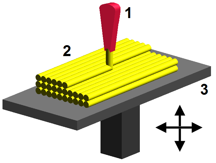
FFF printing is the most commonly used printing technique for entry level 3D printers. The FFF technique forces a material through a heated nozzle to partially liquefy it; the semi-solid material is then deposited by robotic means in a layered pattern to produce a part. Most FFF machines use spools of ABS or PLA plastic as their printing material. Makerbot, Solidoodle, and Rep-Rap 3D printers all employ the FFF technique.
Overhangs are Risky
Printing an overhang with a FFF printer requires that the outer perimeter of a print layer be deposited partially unsupported. Most FFF printers advertise a “maximum overhang angle” that they are capable of printing, and most are able to achieve this angle under certain circumstances; however, overhangs on parts are one of the most common causes of print failures.
Most parts with overhangs have narrow slender bases and then widen as they go up. The narrower base means that there is less surface area connecting the part to the build platform. The movement of the print nozzle across the top layer of a part produces significant lateral forces that can dislodge a part from the build platform and ruin a print. A narrow base significantly exacerbates this problem. When printing a part that widens significantly from a narrow base, I recommend using a raft. Rafts are a common feature of most 3D printing software packages; they automatically add an extended base to the bottom of a print, in an attempt to prevent dislodgement. However, rafts require additional print time and often disfigure the bottom layer of a part. A better solution is to design the part from the beginning to avoid significant overhangs.
Even if a part has a wide base, overhangs can still cause difficulties. When the print head is printing the unsupported portion of an overhang it is more sensitive to disruptions. Temperature changes in the environment, induced vibrations from the movement of the printer, and defects in the plastic filament are all more likely to cause a disruption at this point. These disruptions can result in either too little or too much plastic being laid down. When not printing an overhang either of these defects would typically be automatically resolved by the stable nature of the printing process. However, these minor disturbances become unstable when printing an overhang. A small gap in one part of an overhang results in the next layer being deposited with less support than expected. This can result in a “spaghetti noddle” effect where the lower layer does not have enough material to catch the next layer and the plastic is extruded into space (forming the visible “spaghetti noddle” pattern) . When this happens catastrophic failure of the print often results as each subsequent layer has even less support than the prior layer.
Higher end FFF printer’s print a secondary support structure beneath overhangs to support the fresh layers; this secondary structure must then be removed by hand afterwards. The removal of the support structure is in general a time consuming process, and not cost effective for large batch parts; therefore, avoiding the use of overhangs is beneficial even on printers with support material capabilities.
While overhangs are sometimes unavoidable designers of 3D printed parts should be aware that the presence of overhangs increase the risk of print failure. When printing with overhangs, decreasing print speed, decreasing print resolution, and using a raft can all increase print reliability; however, if a designer can avoid overhangs in a part they can significantly increase its printability. Greater printability means a part will be more economical to produce and produced parts will have fewer defects. To test the ability of print to print overhangs I recommend using this file: Overhang Calibration
Use Bridges
A bridge is very similar to a overhang in that it requires material to be deposited unsupported; however a bridge runs between two points instead of extending beyond the existing perimeter of a part. Bridges are printed by tensioning the freshly extruded filament behind the print head until the extruder head reaches the destination point. Bridges can range in length from a few millimeters to maybe 5 inches in length, and work at almost any width. Longer bridges have higher risk than shorter bridges, and a poorly calibrated printer will have significant problems printing bridges. This video depicts a low end FFF printer creating a bridge.
Printing a single bridge layer is significantly more risky than printing a single overhang layer; however, one bridge layer can often accomplish the same amount as 100 layers of overhang. When needing to span a space a bridge will typically have less net risk than straight overhang or fillet. Less risk results in higher printability and more economical parts.

To test the ability of your printer to print bridges I recommend using this file: Bridge Calibration
Interior Structure Matters
A critical parameter for a part produced on an FFF printer is the Infill Density. This parameter specifies how hollow or solid the internal structure of a part will be. Most FFF printers will fill the interior space of a part with a honeycomb structure, and will vary the size of the hexagonal cells to adjust the infill density. The higher the infill density the smaller hexagonal cells and the more plastic that is used to produce a part. Hexagonal is the most common infill pattern, and the pattern that i most frequently use, but other patterns do exist.
When designing a 3D printed part where strength is a concern, many people fall into the trap of increasing the infill density. Increasing the infill density does increase the strength of a part, but significantly less than you might expect. It seems right to follow the logic that if I double the amount of plastic in a part I should roughly double the strength; however, in practice what occurs is that doubling the amount of plastic in a part will never double the strength, and may in fact reduce it. This is a result of two seldom understood effects of the FFF process: thermal stresses, and air cell strength.
When FFF filament is cooled after being extruded, it shrinks. The actual volumetric change is highly depended on print temperature and plastic type. In general hotter prints shrink more, and ABS plastic shrinks more than PLA. ABS shrinks so much that almost all ABS printers keep the part heated during the printing process to reduce the thermal shock of cooling. As the extruded plastic shrinks it creates internal stresses within the part. When the infill density of a part is increased the magnitude of these internal stresses is increased. Larger prints, and denser prints will both experience significantly more thermal stress and thermal warping than smaller, lighter prints. This significantly reduces the gains achieved by increasing the infill density.
The internal honeycomb structure of a 3D printed part actually does a great deal to increase the strength of the part. The flexible nature of PLA and ABS plastic, and airtight printing process results in each internal cell acting a pressure chamber. The internal pressure produced by deformation of a 3D printed parts is able to distribute forces over a wide area, and reduce local critical stresses. Increasing the infill density decreases the flexibility of the pressure chambers, reducing their ability to distribute force, and thereby reducing the strength gain. While there are several different internal patterns used by 3D printers I know of no effective study that has compared their relative strengths. Below you can see some examples of different infill patterns:
In general low infill density part designs will have higher printability, due to the decreased warping. They will also have greater strength-per-mass, further increasing their economic efficacy. When designing a part for 3D printing, low infill density should be used except in critically space limited applications.
General Tips:
Drill Holes Manually
3D printers are never able to exactly reproduce the requested dimensions of a design. Slight overflow from the nozzle results in overlarge exterior dimensions and decreased interrior dimensions; underflow produces the reverse effect. 3D printer part tolerances are generally not published for FFF machines, and are often design dependent. Typically this does not cause problems, but for shafts, bolts, and screws slight variations in hole size result in massive performance changes. Instead of designing the 3D model of the part with the exactly correct hole sizes, shrink all hole sizes by approximately 5-10%, and plan on manually drilling the holes. This prevents minor changes in printer calibration from affecting part performance. Remember, that this means you have to leave access to the hole for drilling; never put a hole where a drill can’t reach it.
ABS Acetone Smoothing
Applying acetone to ABS printed parts erodes the surface of the material and produces a smooth mirror like finish. The process requires some practice to get perfect, but can significantly increase the aesthetics of a print. However, if you part is not airtight, acetone can seep into the internal structure of the part and erode your part from the inside. Never acetone wash a strength critical part. PLA plastic is not eroded by acetone, and acetone smoothing on PLA parts should not be attempted. Always use acetone in a well ventilated area. For more information on this topic see here: http://www.3ders.org/articles/20130226-smooth-surfaces-of-abs-3d-printed-parts-with-acetone-vapor.html
Strength Prediction
Numerically engineering a 3D printed part is almost impossible. Finite Element Analysis (FEA) is extraordinarily difficult to perform on the complex interior structure of a part. Furthermore, variations between printers, plastics, and software, results in no useful published strength properties of FFF materials. In my experience the fastest and most economical method for designing a strength critical part is to: design the part, test its strength, and iterate.
The Long and the Short
3D printed parts designs have some surprising and non-intuitive properties. Optimizing a mechanical design for 3D printed production is a complicated and non-trivial task. The extreme ease of part production means that experimentation and iteration are the allies of a 3D printed part designer. Be mindful that design techniques from other fields do not always produce the same results for 3D printed designs, and that the economics of 3D printed production are vastly different.